Coursework · Embedded Systems
Embedded Systems & Digital Compass
Through a sequence of hands-on embedded systems labs, I developed experience connecting hardware components to the ATmega328P and programming their behavior in AVR assembly and C. The course culminated in a two-person final project that combined a magnetometer, LCD, directional LEDs, push-button controls, and mixed-voltage I2C communication into a digital compass prototype.

Project overview
Building Hardware and Software as One System
This project collection demonstrates the progression from controlling individual outputs to building an interactive sensor-based system. The labs covered seven-segment displays, shift registers, rotary input, timers, interrupts, PWM, LCD communication, serial communication, and analog-to-digital and digital-to-analog conversion.
The final project brought many of those skills together in a digital compass prototype. The system read magnetic-field measurements from an MMC3416xPJ magnetometer, calculated a heading, displayed the direction and degrees on an LCD, and illuminated an LED corresponding to north, east, south, or west.
Collaboration
Developed in a Two-Person Team
The labs and final project were collaborative efforts completed as part of ECE:3360 Embedded Systems at the University of Iowa. We worked together to construct and test the hardware, write and debug firmware, and document the results across the full project sequence.
I developed confidence in combining circuit construction with register-level programming, and the team’s shared work helped us test communication interfaces, debug hardware and software issues, and integrate multiple subsystems into one working prototype.
- Collaborated on breadboard circuit construction and component integration
- Wrote and debugged AVR assembly and embedded C
- Used datasheets to configure microcontroller registers and external devices
- Integrated user inputs, displays, sensors, and communication interfaces
- Tested circuits using serial output, a multimeter, and an oscilloscope
- Documented hardware, software, calculations, testing, and results
- Diagnosed problems across both hardware and software
Featured project
Digital Compass Prototype
The final project goal was to determine cardinal direction and rotational heading while allowing the user to activate or deactivate the system.
Hardware used
- ATmega328P microcontroller
- MMC3416xPJ three-axis AMR magnetometer
- 16×2 LCD
- Four colored directional LEDs
- Debounced push-button switch
- Two 2N7000 N-channel MOSFETs
- Pull-up resistors and mixed-voltage level shifting
- Breadboard circuitry
Key behaviors
- The LCD initially displayed "PRESS BUTTON TO BEGIN."
- Pressing the button activated or deactivated the compass.
- When active, the program retrieved sensor measurements and calculated the heading.
- The LCD displayed the cardinal direction and heading in degrees.
- A corresponding LED indicated north, east, south, or west.
- The display updated when the calculated direction changed.
Integration
Hardware and Software Integration
Sensor input
MMC3416xPJ magnetic-field measurements were captured and interpreted as heading data.
Communication
Bidirectional I2C communication linked the magnetometer to the ATmega328P.
Voltage compatibility
MOSFET-based level shifting allowed the 3.3V sensor to communicate safely with 5V logic.
Processing
Heading and cardinal-direction calculations were performed in embedded C on the microcontroller.
User interface
The LCD, directional LEDs, and push button provided visible feedback and interaction.
Visuals
Lab Gallery
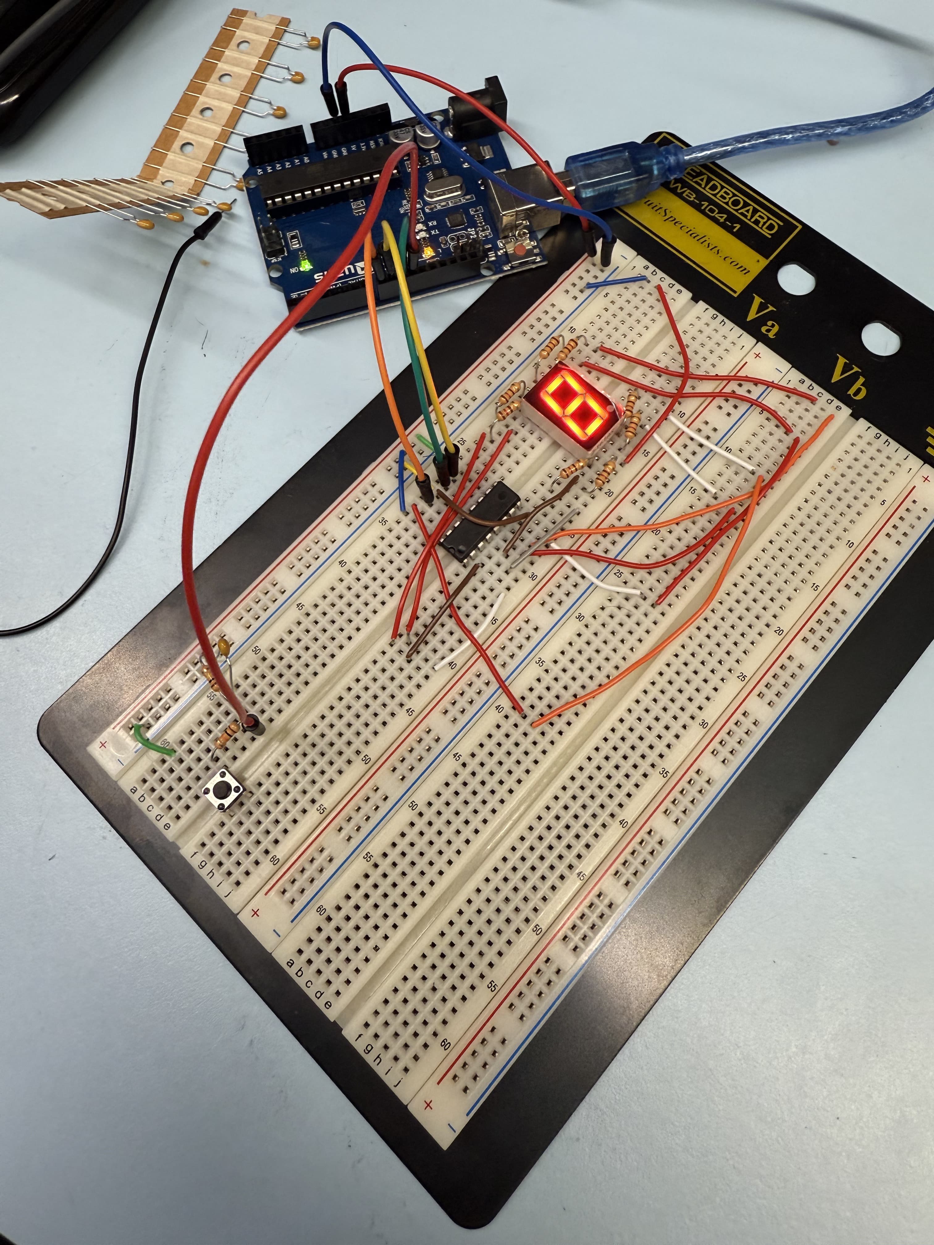
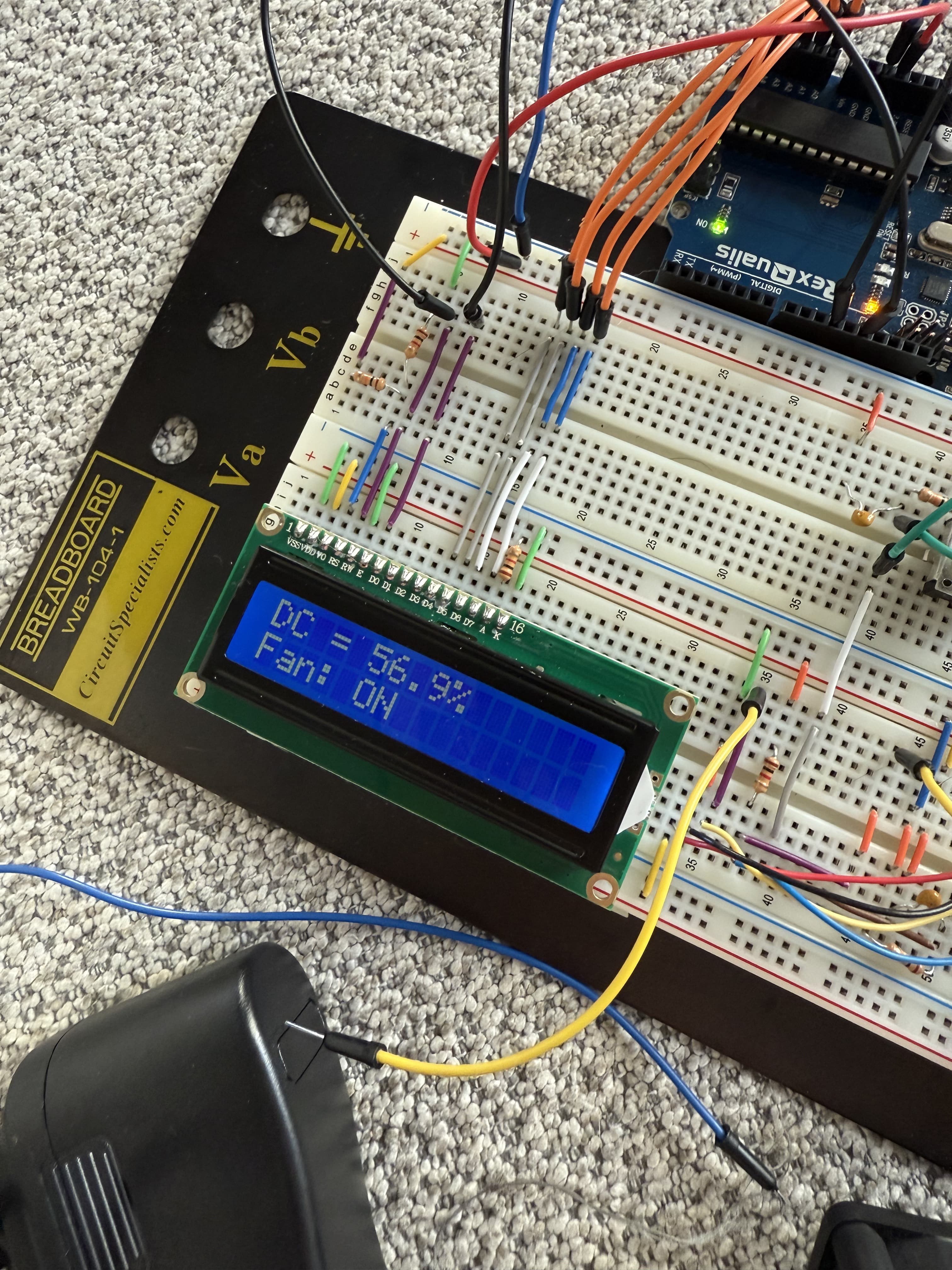
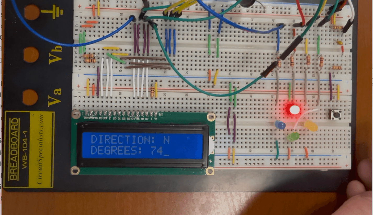
Lab progression
Lab Progression
Hexadecimal Up/Down Counter
Built a hexadecimal counter using the ATmega328P, an SN74HC595 shift register, a seven-segment display, and a debounced push button. AVR assembly lookup tables stored the display patterns for 0–F, while the duration of each button press controlled incrementing, decrementing, mode changes, and resets.
- AVR assembly
- Shift registers
- Lookup tables
- Button timing
- Hardware debouncing
- Seven-segment displays
Rotary Encoder Interface
Extended the counter with a rotary pulse generator, using quadrature-state changes to determine clockwise and counterclockwise rotation. The lab introduced input masking, timer calculations, and multi-input interaction.
- Quadrature input
- Timers
- Input masking
- Rotary controls
- State tracking
PWM Fan Controller
Created an interactive cooling-fan controller using Timer/Counter0 PWM generation. A push button controlled the fan’s power, a rotary input adjusted its duty cycle, and an LCD continuously displayed the fan status and duty-cycle percentage.
- PWM
- Pin-change interrupts
- LCD communication
- Duty-cycle calculations
- Rotary input
- AVR assembly
Serial Data Logging System
Developed a serially controlled analog data-logging system in C. The system used the ATmega328P’s ADC to measure voltages, a MAX518 DAC to generate output voltages, USART for computer communication, and I2C for external-device control.
- Embedded C
- USART
- ADC/DAC
- I2C
- Command parsing
- Serial communication
Testing
Testing Across Hardware and Software
We tested components separately before combining them into the final system. Serial output helped trace communication with the magnetometer, while a multimeter and oscilloscope were used to verify voltage levels, I2C activity, and level-shifter behavior. This component-by-component approach made it easier to isolate wiring, timing, and communication problems.
- Incremental integration
- Datasheet interpretation
- Register-level debugging
- Circuit verification
- Hardware/software fault isolation
- Testing mixed-voltage communication
Challenges
Challenges and Limitations
Mixed-Voltage Communication
The magnetometer operated at 3.3V and was not tolerant of the microcontroller’s 5V logic. The team constructed a bidirectional I2C level shifter using 2N7000 MOSFETs and pull-up resistors.
Sensor Reliability
The magnetometer did not always provide stable heading measurements, even when tested with reference libraries. This limited the consistency of the degree output and reinforced the importance of calibration and sensor validation.
I2C Error Handling
A missed acknowledgement could cause communication to stop and require the prototype to be restarted. A future version would include timeouts, retries, and more robust recovery behavior.
Experience
Skills Demonstrated
- Embedded systems
- AVR assembly
- Embedded C
- ATmega328P
- Register-level programming
- I2C
- USART
- PWM
- ADC/DAC
- Interrupts
- Timers
- LCD interfaces
- Sensor integration
- Circuit construction
- Hardware debugging
- Datasheet interpretation
- Technical documentation
- Team collaboration
Project status
Completed
These projects strengthened my ability to reason about software and hardware together. I gained experience moving from circuit diagrams and datasheets to working prototypes, debugging communication at the register and signal levels, and integrating several components into one interactive embedded system.